Distance field transparency
2 Jun 2023Rendering images with transparent pixels
Textures and sprites with (partially) transparent pixels are often used in computer graphics to add details to assets that aren't part of the asset shape. For example, grass rendering often makes use of textures containing many grass blades, instead of modelling every grass blade individually. This has performance benefits and allows artists to add lots of small details to the scenery.
Contrary to the shape of 3D models, the edges of these details become jagged and pixelated when zoomed in. If you look close enough, the separate pixels can be told apart. This can be mitigated by using higher resolution assets, but this hurts performance. To fix this problem, this article goes into generating signed distance fields, which can be used instead of pixel alpha values to define shapes on an image. This technique was popularized by Valve in 2007 with this paper, who used it for glyphs and fonts in Team Fortress 2. Nowadays, the technique is often used for foliage rendering and rendering text in real time graphics when drawing vector graphics is too slow.
Using SDFs over the alpha channel for transparency has several advantages:
- Smooth shape outlines which don't ever become pixelated when magnified
- The SDF data fits into the alpha channel of a texture, so no new data needs to be allocated.
- SDFs are very fast to use. They won't degrade performance and don't require extra memory.
- The technique allows for anti aliasing on the edges at every zoom level, which is not possible with normal transparency.
- Even at lower resolutions, SDF shapes retain a high level of detail.
- SDF edges look the same regardless of rotation, there are no grid-like artifacts.
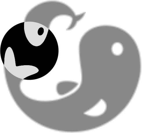
Figure 1 shows a low resolution (125 by 125 pixels) texture of the Koi Farm logo which contains a signed distance field in its alpha channel. The part inside the black circle uses the SDF to render smooth edges, based on a high resolution version of this logo.
There are drawbacks too:
- SDFs can only store information about fully opaque shapes. There can't be partially transparent pixels on a texture that contains a SDF in its alpha channel.
- SDFs need to be generated using a higher resolution version of the asset. This is only a problem if the input image is a raster image, since vector images can always be magnified.
Signed distance fields
Signed distance field calculate for every pixel on the output image how far the center of that pixel is removed from the actual edge from the image. This is either a positive or a negative distance, since a pixel can be either inside or outside the shape described by the SDF. That's why the distance field is signed. If the distance towards the edge is negative the pixel is outside the shape, and if it's possible the distance is positive.
Because pixel opacity is stored in just one byte, this value is stored in the range $[0, 1]$ just like the three other color channel values are stored, where $0.5$ is the edge, so if the distance is $<0.5$, a pixel is outside the shape.
Rendering textures with SDFs is therefore fairly straightforward; the texture can be sampled normally using linear interpolation (and mipmapping if mipmaps are generated), and the alpha value is interpreted as the signed distance. If it is lower than $0.5$, the pixel should not be rendered, and if it is higher, the pixel should be opaque.
Generating SDFs
To generate SDFs, I have created an online tool called SDF maker. It takes either raster images or vector images and converts them to images with SDFs with a configurable output resolution and SDF radius. This paragraph explains how the tool was developed. The source code for this tool is released on GitHub under the MIT license.
While generating assets using tooling like this and shipping the resulting assets works well, it may also be useful to generate signed distance fields at runtime. Luckily, the algorithms used by this tool are fast enough to use live.
SDF maker requires a high resolution version of the texture that needs to be converted. The resolution must be higher, because the SDF essentially stores a higher resolution shape than the lower resolution could otherwise contain. The algorithm performs the following steps to produce the lower resolution image with a SDF:
- The high resolution source image is read.
- The algorithm creates two Voronoi diagrams using the Jump Flooding Algorithm, one seeded with all opaque pixels and another one seeded with all transparent pixels. These Voronoi diagrams store the coordinates of both the nearest opaque and the nearest transparent pixel for every pixel. Since a pixel is either opaque or transparent, one of the diagrams always contains the current pixel coordinate, and the other diagram always contains another coordinate.
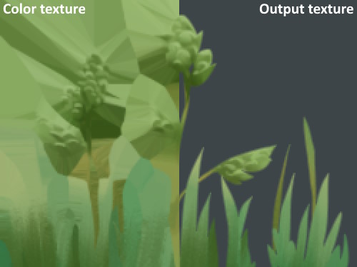
- A color texture is created. This texture has the same resolution as the input image, but every transparent pixel stores the color of the nearest opaque pixel instead. This is crucial for mipmapping, as explained in the next paragraph. The left half of Figure 2 shows how this color texture looks. This texture can be created using the Voronoi diagram containing the coordinates of the nearest opaque pixels.
- Mipmaps are generated for the color texture, which is then downscaled and rendered to the output image in the output resolution using mipmapping for downscaling.
- The distance to the edge is calculated from the Voronoi diagrams and stored on the output image. For every transparent pixel, the distance to the nearest opaque pixel is queried from the diagram, and every opaque pixels reads the distance to the nearest transparent pixel.
The radius of the stored distance can be changed as well. If rendering a shape is enough, the radius can be $1$, since no extra information is needed. If the rendered textures need an outline of several pixels wide, the SDF radius can be increased to store enough information for outlines.
Mipmapping
Most 3D renderers use mipmapping on textures to improve visual quality and performance. This means the texture is stored at lower resolutions, which are sampled when the texture is viewed from a distance or at an angle.
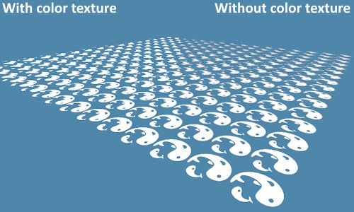
Downscaling textures with transparent regions can cause problems. Transparent regions naturally have no color, but these pixels have a color value nonetheless - it's just not visible. These "invisible colors" blend into neighboring pixels when downscaling however, causing the issue demonstrated on the right half of Figure 3. The transparent pixels were black. The texture should still contain white shapes in the distance, but they now become darker and muddy because the black transparent pixels blended into the visible white pixels.
That's where the color texture from Figure 2 comes in. The transparent pixels assume the color from the color texture, which is the color of the nearest opaque pixel. The resulting texture now has proper colors, even when sampled at lower mipmap levels. The left half of Figure 3 shows a texture with proper colors on the transparent pixels.
Anti aliasing
Another advantage of SDF based transparency is the possibility to anti-alias the edges of shapes described by the SDF. Without anti-aliasing, the GLSL shader code to query opacity would look something like this:
vec4 pixel = texture(source, uv);

vec4 color = vec4(pixel.rgb, step(0.5, pixel.a));
In this case, the alpha value of the color pixel will be either $0$ or $1$ (depending on which side of $0.5$ it's on), creating sharp non aliased edges. Anti aliasing can be achieved by ramping from $0$ to $1$ over the length of one pixel, which can look like this in GLSL:
vec4 pixel = texture(source, uv);

vec4 color = vec4(pixel.rgb, clamp((pixel.a - 0.5) * 2.0 / fwidth(pixel.a), 0., 1.)));
In this example, the fwidth function is used to make sure the ramp is the same for all edges regardless of their location in the scene; zooming in on edges won't make them more blurry.
Conclusion
The SDF maker tool has been very useful to me to create vegetation assets. This seems to be the most practical use of this technique, although it is also very useful for rendering transformed text in 3D environments, as the original paper by Valve demonstrated. I can also imagine many 2D applications, where SDFs can be used instead of vector graphics, which are much slower to render.
Using jump flooding to generate the SDF from Voronoi diagrams turned out to be surprisingly performant, although I wonder whether there are still faster ways to do it. These diagrams are not only useful for calculating the distance to the nearest edge, one of the diagrams could also be reused to quickly construct the color texture, assigning the most appropriate color to every transparent pixel.
One caveat of the Jump Flooding algorithm is that it is has a very small error rate. The errors are typically small and unnoticeable, but a pixel may be off now and then. To reduce the error rate, I have implemented the variant 1+JFA in SDF maker, which reduces the error rate significantly at the cost of one extra pass.